You can find the article of our factory manager Dr. Yaşar Mutlu, which appeared in Valve World's November issue, below.
Introduction
Fluid control and its automation is one of the main issues in valve industry. One of the fluids who its transport and control makes big challenges in this sector are Cryogenic fluids. In literature the fluids with the temperature less than -150℃ are called Cryogenic fluids. Medical sector (Cryosurgery), Food industry (frozen foods), biology researches (Cryobiology), electronic industry (Cryoelectronics), gas production (Fractional Distillation), petroleum and natural gas industry (LNG production) are some of the main fields which cryogenic fluids are used.
This paper is about the design of TORK cryogenic solenoid valve and low temperature effects on solenoid valve efficiency.
Purposes
Like other process industry automation field solenoid valves are used very commonly in cryogenic fluid control industries. The main challenges for the design of a solenoid valve suitable for cryogenic applications are as follows:
First the sealing. In cryogenic valves because of low temperatures using rubber base sealing materials are impossible. So, finding and using suitable sealing material is one of the main issues in cryogenic fluid controls.
The second aspect is choice of body material. In cryogenic valves, cryogenic fluid is in contact with the valve body. Cryogenic fluids’ low temperatures may change the mechanical strength and frailty of materials. So, selecting suitable body material is also one of the main problems in design of Cryogenic solenoid valves.
Heat Transfer
Heat transfer also comes into play. Prepare of cryogenic conditions is not so easy and it needs high energy values. So, minimization of heat transfer in cryogenic equipment is an important issue in the design of cryogenic solenoid valves. In this study, minimization of heat transfer is one of the main issues.
The fourth aspect is Magnetic Field Efficiency. Solenoid valves work with the help of magnetic field which produced by a coil. Also, when the temperature decrease, coils’ wire resistance also decreases and conductivity increases. On the other hand, low temperature affects the magnetic permeability of ferritic steels which are used in solenoid valves. So, researching about these effects is one of the main topics of this study.
Finally, there is the issue of pressure loss. Like in other mechanical installations, pressure loss is an important issue for the valves. In this study, we have tried to be designed the valve using CFD software to minimize pressure loss.
Comprehensive search
Our design process started with the comprehensive search regarding the materials that are suitable for cryogenic conditions. Materials are chosen according to their thermal expansions, heat conductions, specific heats and their elasticity modulus.
For materials stainless steel was considered. Stainless steel is commonly used in cryogenic applications because of its low thermal conductivity and good mechanical properties. For body part of the valve, brass can also be used because of their capability to retain its ductility, toughness and impact resistance at cryogenic temperatures.
Two phased flow
Regarding sealing elements, as mentioned before, rubber base sealing materials can’t be used for cryogenic applications. PTFE is one of the materials which retains its physical properties and stays stable in cryogenic conditions.
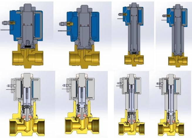
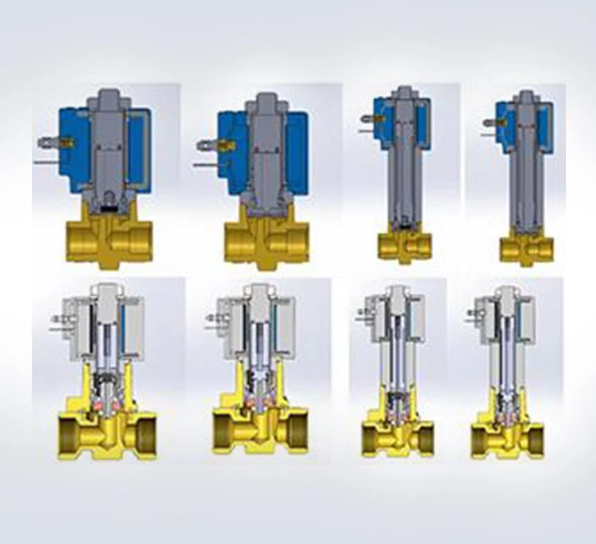
Figure 1: First designs using CAD software.
It is known in direct operating solenoid valves that plunger opens and closes the orifice directly. But in pilot operating valves, diaphragms are used for sealing of the orifice. On the other hand as mentioned before, rubber based materials can’t be used as a diaphragm in cryogenic valves. Because of that, pistons with special graphite filled Teflon rings are used for sealing of the pilot operating valves orifice.
One of the important issues for cryogenic valves is the two phased flow. In cryogenic applications, fluid may be boil due to the change in pressure or heat transfer.
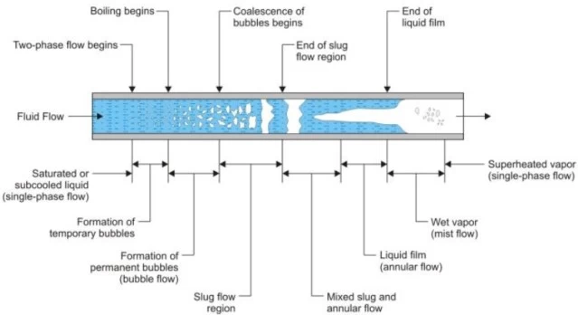
Figure 2: Progress of the boiling along a pipe.
To reduce the heat transfer, design of the cryogenic valves has been changed related to the normal condition valves. For this propose first of all coils which are the main heat sources were held away from the body with the help of longer tubes so that effect of the coils’ heat will have less impact on phases of the fluid. Longer tube designs can be seen in Figure 1.
As a second step computational flow analysis is used to understand the pressure losses, total heat transfers and phase changings in the valves as well as calculating Kv values. Boundary conditions can be seen in Table 1.
Figure 3 shows the static and total pressure contours and Figure 4 shows the velocity contours.
Port Size | Fluid | ||||
G1/2 | Liquid Nitrogen | ||||
Working Conditions (Domain) | Valve’s Results | ||||
Total Input Pressure (Pa) | Static Output Pressure (Pa) | Total Δp (Pa) | Static Δp (Pa) | Mass Flow (kg/sec) | Velocity (m/s) |
285000 | 0 | 199057 | 200475 | 1,42 | 6,9 |
Table 1: Boundary conditions for computational flow analysis.
Low resistance values
Our analysis proves that change of temperature, decrease or increase the ratio between gas and liquid. Also, it can be seen that velocity increases at the orifice areas. Increased velocity decreases pressure and this leads the fluid to boil when it passes orifice which is not a desired situation.
Figure 3: Total Pressure contours.
As a result of CFD analysis to minimize the pressure losses, design of the orifice optimized and because of that higher Kv values achieved.
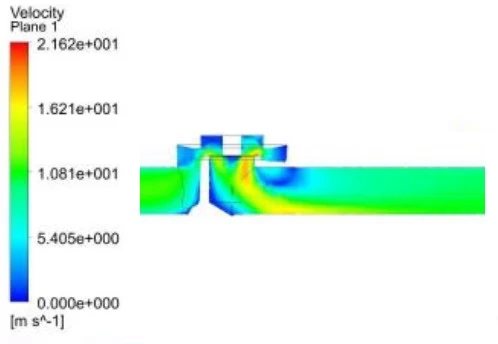
Figure 4: Velocity contours.
Another challenge in cryogenic solenoid valves is the condensation of the weather humidity. This condensation may be cause the short circuit and burn the coil. So, to protect the valve from the condensed water IP68 coils are preferred to use in cryogenic solenoid valves.
Another issue to consider in cryogenic solenoid valves is the low resistance values. As it known resistance of the wires reduced in cryogenic situations. Reduced resistance value leads coils’ to draw excess currents. Analytical formulas are driven to solve this situation. Optimum winding number is formulated for coils that can work in -200°C and samples manufactured for testing.
Magnetic field analysis
Tests showed that after 3 hours, temperatures of 230V AC and 24V DC coils reach steady state conditions. Each coils’ inrush currents and times are found with the help of oscilloscope. These experimental studies shows correlation with the formulated results.
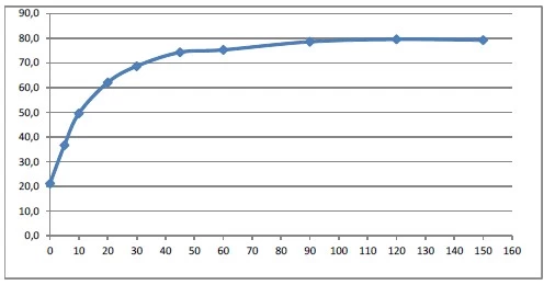
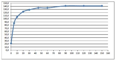
Figure 5: Time-Temperature graph for 24V DC and 230VAC coils.
Also, magnetic field analysis is done for the coils to understand magnetic flux intensity characteristics. Finite element software is used for mesh and solving. Analysis is done for 230V AC and 24V DC coils. Open and close conditions of the coils are modelled and can be seen in Figure 6.
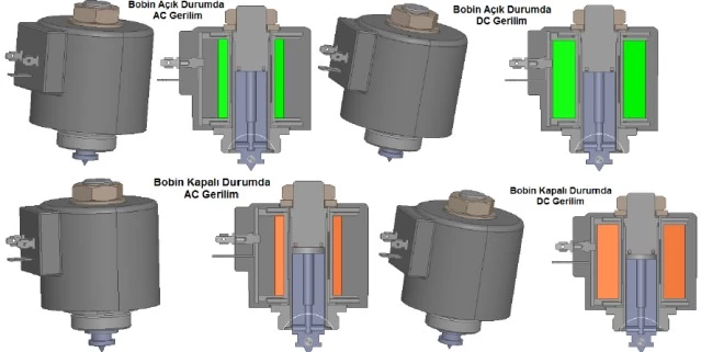
Figure 6: Modelled coils for open and closed conditions.
Material properties of the coils entered to the software. 230V AC coil is meshed to 688277 and 24V DC coil is meshed to 806303 finite elements.
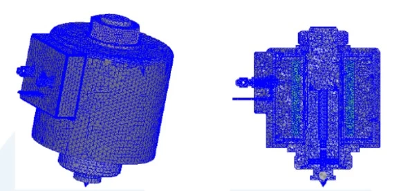
Figure 7: Meshed 24V DC coil.
Time step is set to 0.5 ms for 100 ms. Calculation volume’s dimensions are %100 away from the model’s, filled with vacuum (Figure 8).
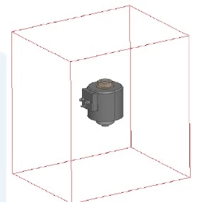
Figure 8: Coil’s calculation space
Analysis temperature is set to -200 C°. Analysis shows that 24V DC coil’s magnetic flux intensity becomes constant after 70 milliseconds. 230V AC coil’s magnetic flux intensity hits maximum and minimum values in 10 milliseconds. It is clear that magnetic flux analysis must be considered for the parts and their material selection progresses.
Conclusion
Cryogenic applications are a vast area but cryogenic environments must be considered cautiously and valves must be designed carefully. Selection of materials, dimensions, coil properties, need to be carefully selected and designed.
CAD program and Fluid Analysis helped to design and test different body parts to decrease pressure losses. Magnetic analysis gave better understanding about materials and its dimensions about the coils. Computational analysis and proving with real time results gives big advantage to design different sized valves and improving the capabilities even more.